Front panel connection

Chat about anything CX16 related that doesn't fit elsewhere
Post Reply
Tmp2k
Posts: 13
Joined: Sun Apr 26, 2020 8:10 pm

Front panel connection

Post by Tmp2k »


Apologies if this has already been discussed but I couldn't find the final spec for the board design (I'm sure it's not set yet anyway).


So I'm talking about the connector you usually find on ATX motherboards that connects to the power and reset buttons and LED etc.

Seriously - why haven't motherboard and chassis makers gotten together to  make a standardized FP block plug??: buildapc

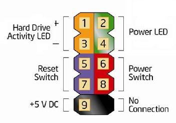
@Kevin Williams I assume the X16 will have this connector in the standard layout, but I have a suggestion that I'd love to see. Can you add on an additional two pins on the end of the header with +5VSB and GND?

This would mean that you could use a single header connector to power a "fancy" front panel via the ATX permanent 5V line. This could be things like capacitive power/reset buttons on the case (which would make case production cheaper and give you more design options)

Kevin Williams
Posts: 15
Joined: Sun May 17, 2020 10:08 pm

Front panel connection

Post by Kevin Williams »


Yes, that's how it's setup.  I also have a seperate 2-pin header for NMI.  The way I have the code in the microcontroller at the moment uses the reset pins on the header for both reset & NMI.  Short push for NMI & long for reset.  It works great, but takes a little getting used too, but I feel like if you're trying to hit NMI and reset instead by accident it would be worse. ?  The screen blanks when you've pushed long enough for reset to happen, so it feels somewhat natural this way.


Tmp2k
Posts: 13
Joined: Sun Apr 26, 2020 8:10 pm

Front panel connection

Post by Tmp2k »


Ah great. Will you be publishing a schematic or a list of all the header pin-outs? 

I realise it's not final yet but it would be great to get a heads up. 

One of the other things I was wondering about were the 2 SNES connector headers. Are these in addition to the rear ones or could they replace them? Do the headers default to P1 and P2? Does anyone have any plans to make a front panel PCB with these connectors? 

Just thinking that having P1 and P2 on the front of the case would be handy. 

TomXP411
Posts: 1760
Joined: Tue May 19, 2020 8:49 pm

Front panel connection

Post by TomXP411 »


1 hour ago, Kevin Williams said:


Yes, that's how it's setup.  I also have a seperate 2-pin header for NMI.  The way I have the code in the microcontroller at the moment uses the reset pins on the header for both reset & NMI.  Short push for NMI & long for reset.  It works great, but takes a little getting used too, but I feel like if you're trying to hit NMI and reset instead by accident it would be worse. ?  The screen blanks when you've pushed long enough for reset to happen, so it feels somewhat natural this way.


That sounds pretty good, actually. There's lots of stuff out there now with that operation mode. Take smartphone power buttons, for example: short press to sleep. Long press to bring up the power down menu. 

Is the NMI going to be similar to STOP+RESTORE on the VIC series computers? 


Post Reply