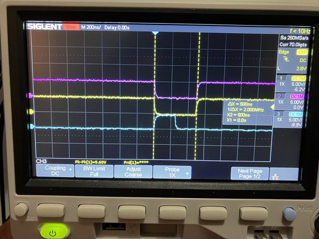
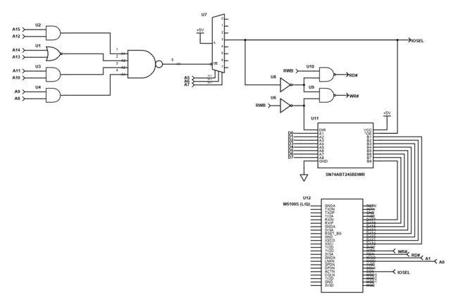
Wavicle wrote: ↑Tue Apr 23, 2024 7:12 am... Your RD# and WR# signals need to be synchronized with PHI2. According to the W5100S datasheet, the parallel bus is sampled when WR# the signal goes low. During a write by the 65C02, the data is not valid until well after RWB goes low.
65C02_Write_Timing.png
You want to latch the write value on the rising edge of PHI2.
And the previous discussion suggests one reason why it may be $9F ... the $95 was on the data bus in the previous cycle, so where the datasheet says "write data invalid", it just so happens that the previous state of the data bus from the read of the high byte address byte in the three byte instruction is still on the data lines.
If the system clock is 100Mhz, the WIZnet chip /write_enable cycle time is a minimum of 40ns (4 system clocks), and the address setup time is 10ns (1 system clock). Both the /WIZ_read and /WIZ_write are a minimum of 1 system clock address set-up with a minimum of 2 system clocks set-up on write to the /WIZ and and a maximum data set-up time of 3 system clocks + 5ns for read from the WIZ.
At +5v, the 6502 bus read cycle has a 10ns set-up time before PHI2 drops and a 10ns hold time after PHI2 drops, and valid data will be available from the WIZ chip for reading 45ns after the later of dropping /CS or /Read_Enable , and remain available until /Read_Enable rises. That is much earlier than the 65C02 bus needs it 10ns before PHI2 falls, and with your circuit the RD# rises with a couple of gate delays after /CS rises on the change of the address bus, satisfying the 6502 bus minimum 10ns hold time.
But if the /CS is not qualified on PHI2=1, then the chip select and write enable is generated as fast as that circuit can generate it, and the data to be written to the WIZ chip must be available 40ns after your IOSELECT goes high and WR# goes low.
If the /WE (your WR#) is qualified by PHI2, I am wondering whether you might be OK.
If you switched to a 2-4 decoder (eg, one side of a 74AC139) to generate WR# and RD#, that might do the job. Supposing you are using side 1, /E1 would be the inverse of your IOSEL, 1A0 would be R/W, and 1A1 would be PHI2, with 1Y2 being WR# and 1Y3 being RD#. Then the addressing and the data to be written to the WIZ chip does not have to be available until 40ns after PHI1 rises, which is well after the tMDS of a maximum of 25ns.
Note that you can use the second half of the decode to invert PHI2 by grounding /E2 and 2A1 and tying 2A0 to PHI1, so that 2Y1 is /PHI1 because %01 -> /Active_Low .(maybe dropping both inverters from your RD# and WR# generation allows you to drop from an octal inverter to a hex inverter).

